Get started
Start with two qubits, then measure and decode a surface-code memory circuit.
Search results
1. Install rstim
Requires Rust and Cargo. Install Rust first.
Install this development version from a repository checkout once. After installation, the commands below work from any directory:
cargo install --locked --path rstim --forceThis install includes all rstim commands used below.
Additional tool for the CSS-code tutorial
The CSS-code tutorial uses the separate qec-code executable. Install it once from the same repository checkout:
cargo install --locked --path qec-code --features cliAdditional tools for decoder replay and optional solvers
The comparison tutorial uses rsinter with two runner features:
cargo install --locked --path rsinter --features rbposd-runner,rmatching-runnerAdd plotting for rsinter plots; it needs native font dependencies. Native HiGHS builds need a C/C++ toolchain and CMake. To enable the optional MLE loss decoder and exact CSS distance solver:
cargo install --locked --path rstim --features ilp --force
cargo install --locked --path qec-code --features cli,distance-ilp-highs --force
rsinter/ilp-runner enables ILP replay; full enables every runner and plotting. Choose only the features needed by your experiment. See feature migration for library defaults.
After installation, restart your terminal and check that it works:
rstim --versionrstim 0.3.02. Define the circuit
Create circuit.stim in your working directory.
cat > circuit.stim <<'STIM'
R 0 1
X_ERROR(0.1) 0
X_ERROR(0.1) 1
CX 0 1
M 0 1
DETECTOR rec[-2]
DETECTOR rec[-1]
OBSERVABLE_INCLUDE(0) rec[-2] rec[-1]
STIM
Render the circuit:
rstim render_svg --in circuit.stim --out circuit.svg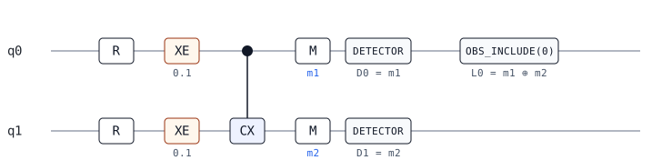
This drawing shows the circuit definition, including both possible error locations; it does not show a sampled result. R resets q0 and q1. Each XE marks an X error with probability 0.1 before the CNOT. M labels the measurements m1 and m2; rec[-2] and rec[-1] refer to those results. DETECTOR defines D0 from m1 and D1 from m2; OBSERVABLE_INCLUDE(0) defines the logical observable L0 = m1 ⊕ m2.
3. Analyze and sample errors
Extract the detector error model (DEM), which lists the effect of each possible error:
rstim circuit dem --in circuit.stim --out model.dem > /dev/null && cat model.demerror(0.1) D0 D1
error(0.1) D1 L0The first row is the effect of an X error on q0; the second is the effect of an X error on q1. The DEM lists only labels that flip, so L0 is absent from the first row because it stays 0.
Sample 10 shots. Each three-bit row is always D0 D1 L0:
rstim circuit detect \
  --in circuit.stim \
  --shots 10 \
  --seed 86 \
  --out-format 01 \
  --append-observables \
  --out events.01 > /dev/null && cat events.01
000
000
110
000
000
011
000
000
000
000110 is the q0-only error; 011 is the q1-only error. A 0 means that detector or observable did not flip.
Render a shot with only the q0 error, matching 110 above:
rstim render_svg --sample_shot --seed 86 --in circuit.stim --out shot.svg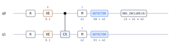
The red X marks the error on q0; there is no red X on q1. Both measurements are 1, so D0 and D1 fire (blue). Their parity is 1 ⊕ 1 = 0, so L0 stays 0.
4. Generate a surface-code measurement circuit
Now use a rotated surface-code memory experiment. Distance 3 gives nine data qubits and eight measurement qubits. The checks are measured for three rounds; the final data measurements define one logical observable, L0.
rstim circuit gen \
  --code surface_code --task rotated_memory_z \
  --distance 3 --rounds 3 \
  --after-clifford-depolarization 0.02 \
  --before-round-data-depolarization 0.02 \
  --after-reset-flip-probability 0.02 \
  --before-measure-flip-probability 0.02 \
  --out surface.stim > /dev/null
rstim circuit stats --in surface.stim
instruction_count: 289
repeat_blocks: 0
max_repeat_depth: 0
num_qubits: 17
num_measurements: 33
num_detectors: 24
num_observables: 1
num_ticks: 22
num_sweep_bits: 0The four 0.02 values set error probabilities at different points in the circuit:
--after-clifford-depolarization: depolarizing errors after Clifford gates.--before-round-data-depolarization: depolarizing errors on data qubits at the start of each round.--after-reset-flip-probability: bit flips after resets.--before-measure-flip-probability: bit flips before measurements.
5. Sample the measurement circuit
Sample one run of the circuit. Save the detector events and actual logical flip separately; the next step uses only the detector events to predict the flip:
rstim circuit detect \
  --in surface.stim --shots 1 --seed 0 \
  --out-format 01 --out surface-detectors.01 \
  --obs-out surface-actual.01 --obs-out-format 01 > /dev/null
paste surface-detectors.01 surface-actual.01
010010100000010000000000 1The 24 bits on the left are detector events (1 means a detector fired); the 1 on the right is the actual L0 flip.
6. Decode the detector results
A decoder predicts whether L0 flipped from the detector events, without seeing the actual L0 bit. Here --decoder rmatching selects the included matching decoder. First derive a detector error model (DEM) from surface.stim; it describes which detector and logical bits each possible fault can flip:
rstim circuit dem --in surface.stim --decompose-errors --out surface.dem > /dev/null
rstim circuit decode \
  --decoder rmatching \
  --dem surface.dem --in surface-detectors.01 \
  --out surface-predictions.01 > /dev/null
cat surface-predictions.011The prediction is 1, matching the actual L0 flip shown above. A logical failure occurs when they differ.
rmatching accepts DEM error components involving at most two detectors. --decompose-errors splits larger components where possible; a remaining component involving three or more detectors (a hyperedge) is rejected.
7. Plot the logical error rate
Repeat the same generate → sample → decode → compare workflow at several physical error probabilities p. A prediction that differs from the actual L0 is one logical failure.
Use the installed rstim command to generate, sample, decode, compare predictions with the actual L0, and write the CSV and SVG plot:
rstim surface-code-ler \
  --distances 3,5,7 --rounds 9,15,21 \
  --physical-error-rates 0.008,0.009,0.01,0.011,0.012 \
  --shots 10000 --seed 86 --out-dir .
The distance and round values pair by position: each circuit runs for three times its distance in rounds. For each p, the command sets all four noise probabilities shown above to p. It samples 10,000 shots per point.
The plot shows an equivalent logical error rate per round. This converts each full-run failure rate to a one-round estimate so circuits of different lengths can be compared.
Physical error probability p | Distance 3 | Distance 5 | Distance 7 |
|---|---|---|---|
| 0.008 | 1.24% | 1.14% | 0.90% |
| 0.009 | 1.60% | 1.48% | 1.29% |
| 0.010 | 1.99% | 1.88% | 1.87% |
| 0.011 | 2.38% | 2.47% | 2.39% |
| 0.012 | 2.77% | 2.94% | 3.07% |

Continue with RustQEC
For lookup, use the CLI reference. For measured results, use the benchmark overview.
Further learning
rstim is inspired by Stim, especially its way of representing circuits and detector error models. It reads Stim-style circuits and implements simulation, sampling, and DEM extraction in Rust so these steps connect with the other tools in this repository.
For more on the matching decoder, see PyMatching. For the code behind the experiment, the Error Correction Zoo introduces the rotated surface code, and Surface codes: Towards practical large-scale quantum computation provides a broader review.